ADT7481
http://onsemi.com
10
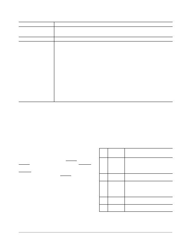
Table 11. CONVERSION RATE/CHANNEL SELECTOR REGISTER (READ ADDRESS 0x04, WRITE ADDRESS 0x0A)
Bit
Mnemonic
Function
7
Averaging
Setting this bit to 1 disables averaging of the temperature measurements at the slower conversion
rates (averaging cannot take place at the three faster rates, so setting this bit has no effect). When
default = 0, averaging is enabled.
6
Reserved
Reserved for future use. Do not write to this bit.
<5:4>
Channel Selector
These bits are used to select the temperature measurement channels:
00 = Round Robin = Default = All Channels Measured
01 = Local Temperature Only Measured
10 = Remote 1 Temperature Only Measured
11 = Remote 2 Temperature Only Measured
<3:0>
Conversion Rates
These bits set how often the ADT7481 measures each temperature channel.
Conversion rates are as follows:
Conversions/sec
Time (seconds)
0000 = 0.0625
16
0001 = 0.125
8
0010 = 0.25
4
0011 = 0.5
2
0100 = 1
1
0101 = 2
500 m
0110 = 4
250 m
0111 = 8 = Default
125 m
1000 = 16
62.5 m
1001 = 32
31.25 m
1010 = 64
15.5 m
1011 = Continuous Measurements
73 m (Averaging Enabled)
Limit Registers
The ADT7481 has three limits for each temperature
channel: high, low, and THERM
temperature limits for
local, Remote 1, and Remote 2 temperature measurements.
The remote temperature high and low limits span two
registers each to contain an upper and lower byte for each
limit. There is also a THERM
hysteresis register. All limit
registers can be written to, and read back from, the SMBus.
See Table 16 for details of the limit register addresses and
power-on default values.
C will result in an out-of-limit condition, setting a flag in
the status register.
If the low limit register is programmed with 0癈,
measuring 0癈 or lower will result in an out-of-limit
condition.
Exceeding either the local or remote THERM
limit asserts
THERM
low. When Pin 8 is configured as THERM2
,
exceeding either the local or remote high limit asserts
THERM2
low. A default hysteresis value of 10癈 is
provided that applies to both THERM
channels. This
hysteresis value may be reprogrammed.
It is important to remember that the temperature limits
data format is the same as the temperature measurement data
format. So if the temperature measurement uses the default
binary scale, then the temperature limits also use the binary
scale. If the temperature measurement scale is switched,
however, the temperature limits do not automatically
switch.
The user must reprogram the limit registers to the desired
value in the correct data format. For example, if the remote
low limit is set at 10癈 and the default binary scale is being
used, the limit register value should be 0000 1010b. If the
scale is switched to offset binary, the value in the low
temperature limit register should be reprogrammed to be
0100 1010b.
Status Registers
The status registers are read-only registers, at
Address 0x02 (Status Register 1) and Address 0x23 (Status
Register 2). They contain status information for the
ADT7481.
Table 12. STATUS REGISTER 1 BIT ASSIGNMENTS
Bit
Mnemonic
Function
ALERT
7
BUSY
1 when ADC Converting
No
6
LHIGH
(Note 1)
1 when Local High
Temperature Limit Tripped
Yes
5
LLOW
(Note 1)
1 when Local Low
Temperature Limit Tripped
Yes
4
R1HIGH
1 when Remote 1 High
Temperature Limit Tripped
Yes
3
R1LOW
(Note 1)
1 when Remote 1 Low
Temperature Limit Tripped
Yes
2
D1 OPEN
(Note 1)
1 when Remote 1 Sensor
Open Circuit
Yes
1
R1THRM1
1 when Remote1 THERM
Limit Tripped
No
0
LTHRM1
1 when local THERM
Limit
Tripped
No
1. These flags stay high until the status register is read, or they are
reset by POR.
发布紧急采购,3分钟左右您将得到回复。
相关PDF资料
ADT7482ARMZ-REEL
IC SENSOR TEMP 2CH ALARM 10MSOP
ADT7485AARMZ-R
IC TEMP/VOLT DGL SENS SST 10MSOP
ADT7486AARMZ-RL
IC TEMP SENS DGTL 2CH SST 10MSOP
ADT7488AARMZ-RL
IC TEMP/VOLT DGTL W/SST 10MSOP
ADT7518ARQZ
IC SENSOR TEMP QD ADC/DAC 16QSOP
AT30TS00-MAH-T
SENSOR DGTL TEMP I2C/SMBUS 8WDFN
AT30TSE002B-MAH-T
SENSOR DGTL TEMP I2C/SMBUS 8WDFN
BD3504FVM-TR
IC REG CTRLR SGL POS ADJ 8MSOP
相关代理商/技术参数
ADT7481ARMZ-R7
功能描述:板上安装温度传感器 2 CH TEMP SNSR/ALARM 2 WIRE SMBUS INTRFCE
RoHS:否 制造商:Omron Electronics 输出类型:Digital 配置: 准确性:+/- 1.5 C, +/- 3 C 温度阈值: 数字输出 - 总线接口:2-Wire, I2C, SMBus 电源电压-最大:5.5 V 电源电压-最小:4.5 V 最大工作温度:+ 50 C 最小工作温度:0 C 关闭: 安装风格: 封装 / 箱体: 设备功能:Temperature and Humidity Sensor
ADT7481ARMZ-REEL
功能描述:板上安装温度传感器 2 CH TEMP SNSR/ALARM 2 WIRE SMBUS INTRFCE RoHS:否 制造商:Omron Electronics 输出类型:Digital 配置: 准确性:+/- 1.5 C, +/- 3 C 温度阈值: 数字输出 - 总线接口:2-Wire, I2C, SMBus 电源电压-最大:5.5 V 电源电压-最小:4.5 V 最大工作温度:+ 50 C 最小工作温度:0 C 关闭: 安装风格: 封装 / 箱体: 设备功能:Temperature and Humidity Sensor
ADT7481ARMZ-REEL7
功能描述:IC SENSOR TEMP 2CH ALARM 10MSOP RoHS:是 类别:集成电路 (IC) >> PMIC - 热管理 系列:- 标准包装:1 系列:- 功能:温度监控系统(传感器) 传感器类型:内部和外部 感应温度:-40°C ~ 125°C,外部传感器 精确度:±2.5°C 本地(最大值),±5°C 远程(最大值) 拓扑:ADC,比较器,寄存器库 输出类型:2 线 SMBus? 输出警报:无 输出风扇:无 电源电压:2.7 V ~ 5.5 V 工作温度:-40°C ~ 125°C 安装类型:表面贴装 封装/外壳:SOT-23-8 供应商设备封装:SOT-23-8 包装:Digi-Reel® 其它名称:296-22675-6
ADT7481EBZEVB
功能描述:EVALUATION BOARD ADT7481 制造商:on semiconductor 系列:* 零件状态:在售 标准包装:1
ADT7482
制造商:AD 制造商全称:Analog Devices 功能描述:Dual Channel Temperature Sensor and Overtemperature Alarm
ADT7482ARMZ
功能描述:板上安装温度传感器 2 CH TEMP SNSR/ALARM 2 WIRE SMBUS INTRFCE RoHS:否 制造商:Omron Electronics 输出类型:Digital 配置: 准确性:+/- 1.5 C, +/- 3 C 温度阈值: 数字输出 - 总线接口:2-Wire, I2C, SMBus 电源电压-最大:5.5 V 电源电压-最小:4.5 V 最大工作温度:+ 50 C 最小工作温度:0 C 关闭: 安装风格: 封装 / 箱体: 设备功能:Temperature and Humidity Sensor
ADT7482ARMZ-REEL
功能描述:板上安装温度传感器 2 CH TEMP SNSR/ALARM 2 WIRE SMBUS INTRFCE RoHS:否 制造商:Omron Electronics 输出类型:Digital 配置: 准确性:+/- 1.5 C, +/- 3 C 温度阈值: 数字输出 - 总线接口:2-Wire, I2C, SMBus 电源电压-最大:5.5 V 电源电压-最小:4.5 V 最大工作温度:+ 50 C 最小工作温度:0 C 关闭: 安装风格: 封装 / 箱体: 设备功能:Temperature and Humidity Sensor
ADT7482ARMZ-REEL7
功能描述:IC SENSOR TEMP 2CH ALARM 10MSOP RoHS:是 类别:集成电路 (IC) >> PMIC - 热管理 系列:- 标准包装:1 系列:- 功能:温度监控系统(传感器) 传感器类型:内部和外部 感应温度:-40°C ~ 125°C,外部传感器 精确度:±2.5°C 本地(最大值),±5°C 远程(最大值) 拓扑:ADC,比较器,寄存器库 输出类型:2 线 SMBus? 输出警报:无 输出风扇:无 电源电压:2.7 V ~ 5.5 V 工作温度:-40°C ~ 125°C 安装类型:表面贴装 封装/外壳:SOT-23-8 供应商设备封装:SOT-23-8 包装:Digi-Reel® 其它名称:296-22675-6